
Voltage Loss Formula
Long wire runs waste voltage: motors run hot, LEDs dim and chargers slow down. The voltage loss formula tells you how much — from current, one-way length, wire size and material. This calculator applies it for DC, single-phase and three-phase circuits, in AWG or mm², and suggests a wire size that keeps the drop within your target.
- Free to use
- No sign-up
- Runs in your browser
Voltage loss calculator
Voltage Drop Toolkit
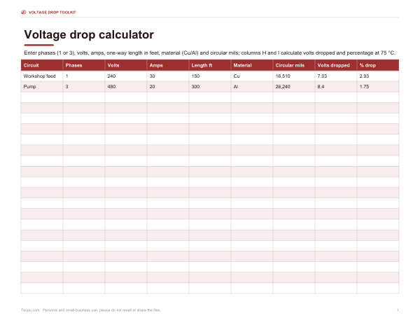
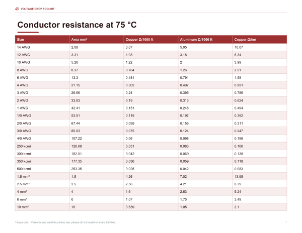
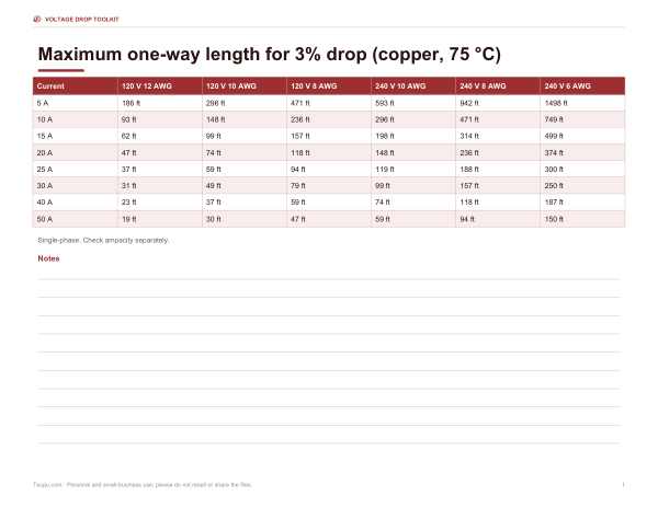
Excel voltage drop calculator for single- and three-phase runs, AWG and mm² resistance tables, maximum-length tables for 120 V and 240 V at 3%, and a wire run planning log.
- Calculator (XLSX)
- Resistance tables (PDF/XLSX)
- Max length tables (PDF)
- Planning log (PDF/DOCX/XLSX)
Formats: XLSX, PDF, DOCX. Instant download after payment (link valid 72 hours, up to 5 downloads). AI-assisted: the templates were drafted with AI help and reviewed and laid out before publishing.
$3.00 USD, one-time 4 files · about $0.75 each
- Instant download
- 7-day refund
- Secure checkout by Stripe
7-day money-back guarantee. Full refund within 7 days of purchase, even after you download.
Free sample: Max Length Tables (PDF, 101 KB)
Full refund within 7 days — see the refund policy and license.
Free printables
Single sheets you can print right now, no sign-up. The full pack adds every sheet in one download plus the editable files.
 Printable Voltage Drop Planning Log
The voltage loss formula
| Circuit | Formula | Why |
|---|---|---|
| DC and single-phase AC | VD = 2 × I × L × ρ ÷ A | Current flows out and back: twice the one-way length |
| Three-phase AC (balanced) | VD = √3 × I × L × ρ ÷ A | Line-to-line drop with balanced phase currents |
| Using K (US) | VD = 2 × K × I × L ÷ CM | K ≈ 12.9 for copper, 21.2 for aluminum (Ω·cmil/ft), L in feet, CM in circular mils |
I is the current in amps, L the one-way length, ρ the resistivity of the conductor and A its cross-sectional area. Percentage drop = VD ÷ supply voltage × 100. The calculator works in metric internally and converts AWG sizes from circular mils (1 circular mil = 0.000507 mm²).
Resistivity and temperature
Copper has a resistivity of about 0.017241 Ω·mm²/m at 20 °C and aluminum about 0.02826; both rise roughly 0.4% per °C. At a typical 75 °C conductor temperature copper reaches about 0.0210 Ω·mm²/m — about 22% more than at 20 °C. That is why voltage drop tables often assume 75 °C, and why the K constants in the US formula (12.9 and 21.2) correspond to warm conductors.
How much voltage drop is acceptable?
In the US, informational notes in the National Electrical Code suggest sizing conductors so that voltage drop is no more than about 3% on a branch circuit and 5% in total for feeder plus branch circuit — a recommendation for efficient operation rather than a mandatory rule in most cases. Other countries set their own limits; for example, the UK wiring regulations give values of 3% for lighting and 5% for other uses on public-supply installations. Low-voltage DC systems such as 12 V solar or vehicle wiring usually aim for 3% or less, because each volt is a large share of the supply.
Maximum run for 3% drop, copper at 240 V
| Current | 12 AWG | 10 AWG | 8 AWG | 6 AWG | 4 AWG |
|---|---|---|---|---|---|
| 10 A | 186 ft | 296 ft | 471 ft | 749 ft | 1191 ft |
| 15 A | 124 ft | 198 ft | 314 ft | 499 ft | 794 ft |
| 20 A | 93 ft | 148 ft | 236 ft | 374 ft | 596 ft |
| 30 A | 62 ft | 99 ft | 157 ft | 250 ft | 397 ft |
| 40 A | 47 ft | 74 ft | 118 ft | 187 ft | 298 ft |
| 50 A | 37 ft | 59 ft | 94 ft | 150 ft | 238 ft |
One-way lengths, single-phase, copper at 75 °C. Halve the lengths for 120 V. Ampacity limits still apply — the table ignores whether a wire is allowed to carry that current.
Worked example
A 30 A, 240 V single-phase feed to a workshop 200 ft away in 8 AWG copper: ρ at 75 °C is 0.0210 Ω·mm²/m, 8 AWG is 8.37 mm² and 200 ft is 60.96 m, so VD = 2 × 30 × 60.96 × 0.0210 ÷ 8.37 ≈ 9.17 V, or 3.82%. That is above a 3% target, and the calculator suggests 6 AWG, which gives 2.40%. At 150 ft, 8 AWG would just pass at 2.86%. The US K formula gives almost the same answer: 2 × 12.9 × 30 × 200 ÷ 16,510 ≈ 9.38 V.
Low-voltage DC systems
At 12 V or 24 V the same wire loses a much larger share of the supply than at 120 V or 240 V, so solar, RV, marine and automotive circuits usually need surprisingly heavy cable. A 20 A load 10 m (about 33 ft) from a 12 V battery on 4 mm² copper drops about 2.1 V at 75 °C — roughly 17% — and would need 25 mm² (about 2.8%) to stay under 3%. Remember that the length in the formula is one-way; the factor of two already covers the return conductor. Many battery and inverter manufacturers publish recommended cable sizes for their products, which take precedence.
Ways to reduce voltage drop
- Use a larger conductor — the most common fix.
- Shorten the run by moving the panel, inverter or battery closer.
- Use a higher voltage: the same power at 240 V draws half the current of 120 V, and the percentage drop falls to a quarter.
- Use copper instead of aluminum for the same size, or upsize aluminum by about two sizes.
- Split a large load across more circuits.
Safety note
Voltage drop is only one part of sizing a conductor. Wires must also be rated for the current (ampacity), protected by the right breaker or fuse, installed by the rules of your local electrical code and, where required, by a licensed electrician. This calculator is for planning and education.
Frequently asked questions
What is the formula for voltage drop?
VD = 2 × I × L × ρ ÷ A for single-phase or DC, and √3 × I × L × ρ ÷ A for three-phase.
What is an acceptable voltage drop?
Commonly 3% for a branch circuit and 5% total in the US; other countries set their own limits.
Is length one-way or round trip?
One-way — the formula’s factor of 2 accounts for the return path.
Why does aluminum drop more voltage?
Its resistivity is about 1.6 times that of copper.
Does temperature matter?
Yes — resistance rises about 0.4% per °C.
Does this replace code sizing?
No. Wire must also meet ampacity and code requirements.
Can I use it for 12 V DC?
Yes — choose DC or single-phase and enter 12 V; low-voltage systems usually need larger wire.
What is the difference between AWG and mm²?
AWG is a US gauge number where smaller numbers mean thicker wire; mm² is the metric cross-sectional area. The calculator converts between them.
Why is three-phase drop lower?
The √3 factor (about 1.73) replaces 2, because the phase currents share the return path.